Cleveland Family Study
17.3.2 Equipment Preparation
Within one day of the lab visit, check equipment and supplies.
- Check that all equipment is cleaned and that the PIB is set up properly.
- Check to be sure you have spare supplies packed.
- Prepare a CD with the Participant ID.
17.3.2.1 Control Module
The Control Module provides an interface for the Patient Interface Box, DC Channel Expansion (this provides 8 to 10 high level DC inputs (±1V)), and two Pressure Transducers for measurement of signals such as nasal airflow, CPAP pressure or esophageal pressure. An integrated serial port allows connection of a Nonin XPod pulse oximeter or the External Device Interface Module which can be used to add up to an additional 15 DC inputs. It is connected to the Host PC by Ethernet cabling and uses TCP/IP network protocol for communication. It also provides the user with impedance indicators for electrode channels.
17.3.2.2 Patient Interface Box (PIB)
The Patient Interface Box (sometimes referred to as a "headbox") is the device that contains amplifiers and filters for proper processing of the physiological signals. All electrodes and probes, other than the oximeter, are connected to this device. The processed signals from this box are sent to the Main Unit by an Analogue cable.
17.3.2.3 Table 1: PIB Configuration for the Family Study
The table below shows the PIB/headbox configuration for Family as it is displayed on the PIB.
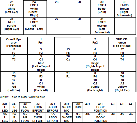
Positive leads are blue on the PIB and Negative leads are black on the PIB.
17.3.2.4 Table 2: Display Name and Wire Descriptions
| Display | Number of Leads with Wire Description |
|---|---|
| Air | Compumedics Triple Thermistor (Blue lead to Blue, White lead to Black) |
| Thor | Thorax Respiratory Band |
| Abdo | Abdomen Respiratory Band |
| Posn | Position sensor |
| Mic | Snore sensor |
| EEG | Four gold cup electrodes (blue, beige, white and purple) |
| ECG | Two snap electrodes (red and white) |
| Leg/L | Paddle Sensor |
| Leg/R | Paddle Sensor |
| EMG | Three gold cup electrodes (brown, beige and orange) |
| EOG/L | One gold cup electrodes (white) |
| EOG/R | One gold cup electrode (purple) |
| EEG-REF | Two gold cup electrodes (beige and red)(A1 and A2) |
| Aux | N/A |
| PtRef | Gray gold cup (pt forehead to the right) |
| GRD | One gold cup electrode (Cz ground)(green) |
Note: You may want to separately gather all right sided electrodes (C4, A2, EOG/R) and all left sided electrodes (C3, A1, EOG/L) and secure them through a styrofoam cup that has had a hole punched into its bottom. This may prevent tangling, and help with easier identification during placement.
Oximeter Probe and Nasal Cannula are attached directly to the Control Module. Both of these use a clear plastic adaptor. The nasal cannula goes into the airflow port, NOT pressure port (the pressure port is for administering CPAP titration which we do not do).
When observing CPAP, use nasal cannula, cut tubing into CPAP mask port. You can tape to secure. Make sure tubing is not obstructed inside mask. If mask does not have ports in mask, then do not do pressure measure at all.
17.3.2.5 Family Study Template and Polygraph Setup
The sampling rate for each channel is the number of samples recorded per second. The maximum sample rate for each channel is 250 samples/sec. The storage rate per hour based on the sampling rates selected is displayed in the lower right hand corner.
17.3.2.6 Table 3: Channels and Sampling Rates for the Family Study
The following sampling rates are to be used for all FAMILY units only.
Epoch length: 30 seconds
| Channel | Name | Sampling Rate (Hz) | Coupling | HP Filter | P-P Range | Imp. Check |
|---|---|---|---|---|---|---|
| 1 | OFF | 0 | AC | 0.15 | 8mV | No |
| 2 | OX | 1 | DC | 0 | Direct | Yes |
| 3 | EEG | 128 | AC | 0.15 | 1mV | Yes |
| 4 | EMG | 128 | AC | 0.15 | 1mV | No |
| 5 | LEGS | 64 | AC | 0.05 | 64mV | No |
| 6 | Sound | 256 | AC | 0.05 | 1mV | No |
| 7 | Respiratory | 32 | AC | 0.05 | 8mV | No |
| 8 | Position | 1 | DC | 0 | 512mV | No |
| 9 | CPAP Pres | 1 | DC | 0 | 2V | No |
| 10 | Nasal Pres | 64 | AC | 0.05 | 2V | No |
| 11 | CPAP FLOW | 32 | DC | 0 | 2V | No |
17.3.2.7 Table 4: Trace Settings for the Family Study
| Channel | Trace | HP Filter | LP Filter | Notch |
|---|---|---|---|---|
| 1 | LOC-A2 | 0.30 Hz | 35 Hz | 60 Hz |
| 2 | ROC-A1 | 0.30 Hz | 35 Hz | 60 Hz |
| 3 | C3-A2 | 1.00 Hz | 35 Hz | 60 Hz |
| 4 | C4-A1 | 1.00 Hz | 35 Hz | 60 Hz |
| 5 | EMG1-EMG2 | 10.00 Hz | 100 Hz | 60 Hz |
| 6 | L Leg | 10.00 Hz | 30 Hz | Off |
| 7 | R Leg | 10.00 Hz | 30 Hz | Off |
| 8 | SNORE | 10.00 Hz | 100 Hz | 60 Hz |
| 9 | NASAL PRES | 0.10 Hz | 15 Hz | Off |
| 10 | AIRFLOW | 0.10 Hz | 15 Hz | Off |
| 11 | THOR EFFORT | 0.10 Hz | 15 Hz | Off |
| 12 | SUM | 0.10 Hz | 15 Hz | Off |
| 13 | ABD EFFORT | 0.10 Hz | 15 Hz | Off |
| 14 | SaO2 | Off | Off | Off |
| 15 | OX STATUS | Off | Off | Off |
| 16 | ECG1-ECG2 | Off | Off | Off |
| 17 | PULSE | Off | Off | Off |
| 18 | POSITION | Off | Off | Off |
7/25/2001 – Changed channel 5 EMG1-EMG2 to HP = 1, LP = 35, and 60Hz = off
8/20/2001 – Changed EMG back to original settings (changed to 256 now back to 128 – original setting)